

Tercio S1
The Tercio S1 bolts to the back of a stepper motor and turns it into a closed-loop axis. A magnetic encoder under the board reads the shaft, and a 20 kHz position loop corrects the motor so it never silently loses a step.
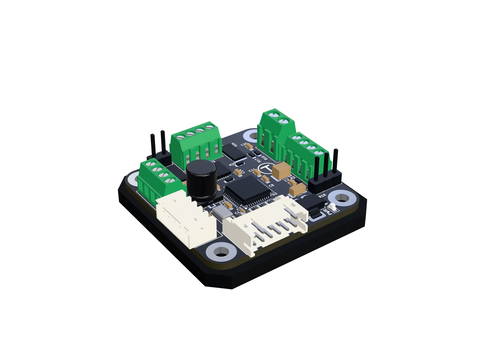
- Driver
- TMC2209, up to 1.77 A RMS per coil
- Feedback
- AS5600 on board, 4,096 counts per turn
- Loop
- 20 kHz position loop, trapezoidal planner
- Bus
- CAN-FD, 500 kbit/s + 2.5 Mbit/s, 127 nodes
- Also
- Step/dir input, two switch inputs
- Supply
- 12–28 V DC
- Board
- 38 × 38 mm
How it works
Section titled “How it works”Every 50 µs, the S1 runs one pass of its position loop:
- 01SenseRead the encoder and unwrap it into a continuous multi-turn position.
- 02PlanAdvance the trapezoidal profile: where the shaft should be now, and how fast.
- 03CorrectThe profile’s speed plus a correction for the error. See Tuning.
- 04DriveA hardware timer turns that speed into steps, up to 500,000 per second.
Because the loop always compares with the encoder, a step the motor misses is simply corrected. If the shaft falls too far behind, because it is blocked or asked for more than it can do, the S1 stops and reports a stall instead of carrying on in the wrong place.
The loop runs from a timer interrupt, independent of everything else the firmware does: bus traffic, flash writes and telemetry never delay it. Tercio Control’s Diagnostics tab shows how much of each 50 µs pass it uses.
- 50µs
- One pass of the loop
- 0.088°
- On-board encoder resolution
- 500ksteps/s
- Step generator limit
- 1.77A RMS
- Maximum coil current
What’s on the board
Section titled “What’s on the board”- Power
- Ground
- Motor
- Bus / data
- Input
- Debug
- Not connected
- Shaft centre (encoder chip on the underside)
Top view, to scale (38 × 38 mm). Hover or tap a connector to name its pins; select it for the full pinout.
Specifications
Section titled “Specifications”Motor and driver
- Motor
- Bipolar stepper, 4 wires, 1.8° (200 steps) or 0.9° (400 steps)
- Current
- Up to 1770 mA RMS per coil (2.5 A peak), set in software in steps of 30–55 mA
- Hold current
- 0–100 % of the run current
- Microstepping
- 1 to 1/256; the driver interpolates to 1/256
- Step rate
- Up to 500,000 steps/s (156 turns/s at 1/16)
Feedback and control
- Encoder
- AS5600 on board, 12 bits, 4,096 counts/turn
- External
- AS5600 (I²C) or AS5048A (SPI, 14 bits)
- Loop
- 20 kHz: feed-forward, PI on position, D on velocity
- Motion
- Trapezoidal moves, velocity mode, synchronised starts, soft limits
- Procedures
- Calibration, homing (switch or hard stop), auto-tune
Interfaces
- Bus
- CAN-FD, 500 kbit/s + 2.5 Mbit/s, 11-bit IDs
- Nodes
- 1–127, 120 Ω termination by jumper
- Telemetry
- 0–1000 Hz: position, velocity, error, state, faults, temperature, supply
- Step/dir
- STEP, DIR, EN, 3.3 V logic
- Inputs
- IN1 and IN2 for limit or home switches, 3.3 V logic
Physical and protection
- Supply
- 12–28 V DC; warns below 8 V
- Protection
- Stall detection, board and driver over-temperature, driver short circuit, command timeout
- Connectors
- 3.5 mm terminal (power), 2.54 mm terminals (motor, CAN, inputs), JST PH 5-pin, JST PHD 12-pin, 2.54 mm headers
- Mounting
- Four M3 holes, centres 30.6 × 30.65 mm
- Board
- 38 × 38 mm